
Ventilation Systems
 Overview
The most expensive part of heating (and cooling) industrial facilities is the large amounts of fresh air that typically must be brought into the facility. This may also be true for other types of facilities, such as office complexes – if the facility is relatively new (built to ASHRAE indoor air quality standards) and includes central power ventilation. A cubic foot of air does not contain much energy, but the high volume quickly adds up.
Buildings should operate at a slightly positive air pressure. This means that the sum of the make-up air must be larger than the sum of the ventilation air. In cases of negative air pressure, the doors will tend to ‘suck closed’, slam or even have a noticeable air flow through them when opened, workers will complain of ‘drafts’, and it will be difficult to exhaust contaminates so the indoor air will likely be dirtier.
Ventilation air is a mandatory component of the HVAC system, both in terms of regulations and reasonable worker safety. It can be a delicate balance between regulations and energy costs, with workers sometime caught in the middle.
It is generally a good practice for the energy auditor to focus mainly on the reduction of ventilation air during UNOCCUPIED periods or when space use has changed. In some cases it may be necessary to recommend an INCREASE in ventilation air as worker safety is more important than energy costs.
Types of Ventilation
There are three broad classifications of ventilation air:
- “Indoor air quality ventilation” used primarily to provide fresh, heated or cooled air to buildings as part of the heating, ventilating and air-conditioning system,
- “Dilution ventilation” which dilutes contaminated air in a whole building or room by blowing in clean air and exhausting some dirty air,
- “Local exhaust ventilation” which captures contaminate emissions at or very near the source and exhausts them outside.
Indoor air quality ventilation is generally provided through the HVAC distribution system, along with heated and cooled air. ASHRAE codes are developed along a ‘CFM per occupant’ for a given activity. HVAC systems are generally designed to provide a ‘percentage’ of outdoor air based on design conditions; better systems will have an ‘occupied’ and ‘unoccupied’ setting that will close or adjust the outdoor air damper setting to reduce the percentage of outdoor air.
Dilution ventilation is usually accomplished with the use of large exhaust fans in the walls or roof of a building or room. It works well where the source of contamination is widely scattered or is from a mobile source, like carbon monoxide from a forklift.
Local exhaust ventilation is needed when the process is with highly toxic chemicals, when there are large amounts of dust, welding fumes, paint fumes, or high humidity conditions such as from a parts washing line.
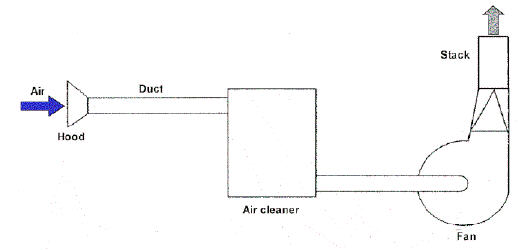
A local exhaust system has five basic elements:
- A “hood” or opening that captures the contaminant at the source,
- Ducts that transport the airborne chemicals through the system,
- An air cleaning device (not always required) that removes the contaminant from the moving air in the system,
- A fan that moves the air through the system and discharges (blows) it outdoors,
- An exhaust stack through which the contaminated air is discharged.
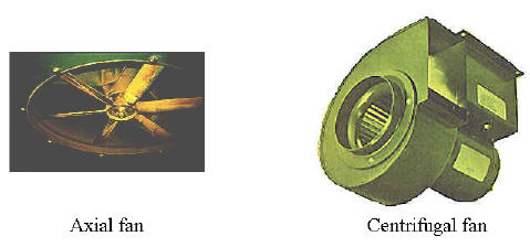
Axial fans are used for ventilating large amounts of air where there is little or no ducting; they are very efficient at moving large volumes of air, but cannot work against much pressure. Axial fans are also much noisier than centrifugal fans. Centrifugal (squirrel cage type) fans are used where it is necessary to produce a suction or work against a pressure, such as in ducted systems. Both types may be direct-driven or indirect-driven with a belt, gears, shaft, hydraulics, etc. Fan blade design will vary with application, such as how much air is to be moved, what is the operating pressure, and is it clean or contaminated air; if contaminated, with what?
Data Gathering
 Ventilation data is generally gathered during the facility walk-thru along with information on the rest of the HVAC system.
For Ventilation systems (exhaust fans) gather the following:
- CFM rating of the fan (if available)
- if CFM rating is not available, attempt to get motor horse-power and type of fan (prop, squirrel cage – centrifugal, etc.,) in order to later estimate CFM
- location of fan
- operating schedule
- control method
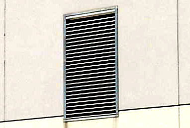
NOTE: Be sure to notice blocked vents, especially if they were designed to provide fresh air make-up to heating systems. It is common to find blocked air vents in furnace and boiler rooms. Maintenance workers often block these vents to reduce drafts and make the space warmer – especially if they must work in or near the space. This could be starving the heating system for air, resulting in reduced efficiency, sooting, and even the production of carbon monoxide.
Estimating Fan CFM
 Fans are often located high on walls, rooftops or other inaccessible areas. It is not critical to know EXACTLY what each fan rating is; however, a reasonable estimate based on a visual of the fan and what the facility maintenance person may be able to provide should be good enough. A little experience and spending some time in manufacturer’s catalogs will make it easier to estimate fan capacities. Use the following samples as a starting point.
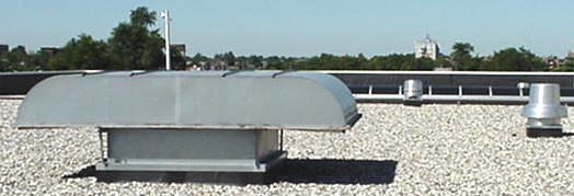
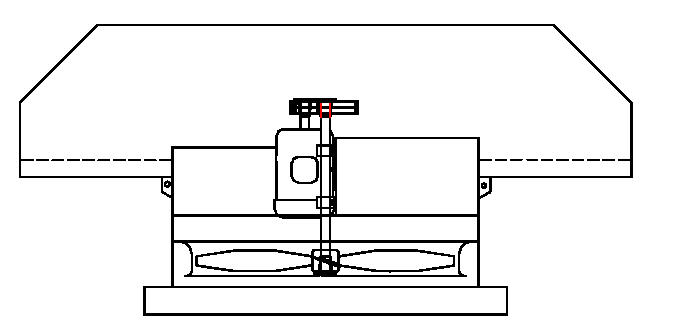
Roof Exhauster – Hoods
24″ Fan @ 1 HP = 6,750 CFM
24″ Fan @ 3 HP = 10,050 CFM
48″ Fan @ 5 HP = 31,093 CFM
54″ Fan @ 10 HP = 45,404 CFM
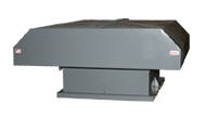
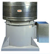 Roof exhauster – Propeller
18″ Fan @ 1/2 HP = 3,930 CFM
18″ Fan @ 1 HP = 4,890 CFM
30″ Fan @ 1 HP = 10,050 CFM
36″ Fan @ 5 HP = 23,610 CFM
60″ Fan @ 20 HP = 73,090 CFM
See more sizes and ratings at the Leader Fan Industries web site linked below.
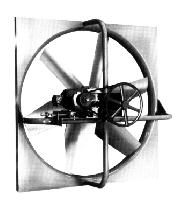
Direct vented axial
20″ Fan @ 1/2 HP = 2,600 CFM
20″ Fan @ 1 HP = 6,000 CFM
36″ Fan @ 3 HP = 28,000 CFM
72″ Fan @ 15 HP = 78,000 CFM
See more sizes and ratings at the Leader and Moffit Corporation web site linked below.
More Information
The American Conference of Governmental Industrial Hygienists (ACGIH®)
See their web site at www.acgih.org for books and other resources on Industrial Ventilation systems
For some typical fan sizes that include both CFH and horse-power rating, see the web site
www.leaderfan.com for assistance with estimating fan ratings, Leader Fan Industries.
Moffitt Corporation www.moffitthvac.com
See also Energy Recovery Wheels and Economizers HVAC
Source: Text Bob Fegan 1/2009; photos Bob Fegan; local exhaust diagram, fan types photo and some definitions from Washington State Department of Labor and Industry web site at www.lni.wa.gov/Safety/Topics/AtoZ/Ventilation/default.asp 10/2004; images and ratings of fan types from www.leaderfan.com web site 10/2004;
© 2008 Energy Solutions Center400 N. Capitol Street NWWashington, DC 20001 All rights reserved. Legal Contact our webmaster