
High Temperature Radiant Tubes
Overview
Heat treating is a high temperature, energy intensive process. The hotter the oven/furnace process temperature, the hotter the exhaust temperatures and the lower the over-all efficiency. Radiant tubes are made of various types of metal alloys or cast ceramic. Burner and tube designs that get more of the heat out of the tube and into the furnace/process have become more common as energy prices increased. This page will contain information about technologies developed to increase burner/tube efficiency.
Tube Inserts
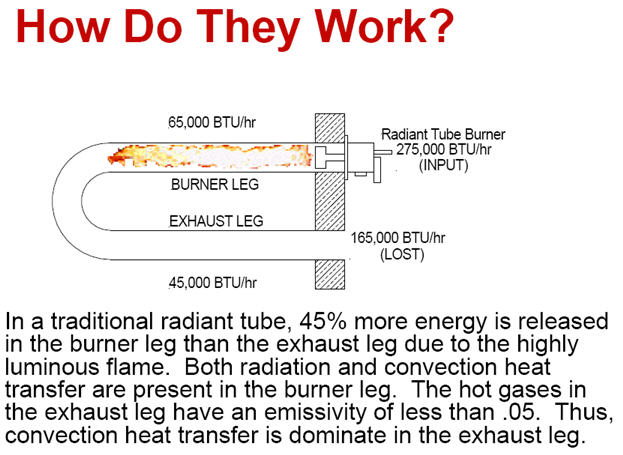
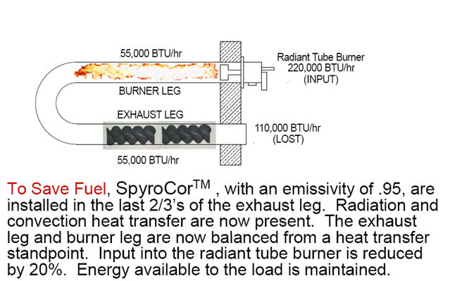
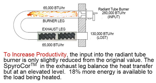
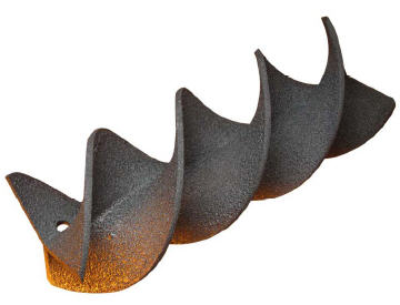
According to Spinworks, savings is generally in the 5 – 20% range and payback is most often less than one year. SpyroCor can also be used on recuperated burners.
More Information
Spinworks, LLC.
5451 Merwin Lane, Suite 207
Erie, PA 16510
Telephone: 814-899-4871
Web site: www.spin-works.com
RASERT Burners
Low NOx Reverse Annulus Single Ended
Radiant Tube Burner (RASERT™)
The 4748 RASERT™ Advantage:
- Increased production through high flux annular combustion
- Fuel savings due to high efficiency integral heat exchanger
- Uniform radiant tube temperatures provide extended radiant tube life
- Low NOx, CO and CO2 emissions achieved by efficient staged combustion, and integral flue gas recirculation
- Designed to be adaptable to existing straight radiant tubes
- Compatible with many existing control systems including simple cross-connected regulator systems
- Built-in air/fuel metering and gas limiting orifice valve mean easier installation and commissioning
- Direct spark ignition
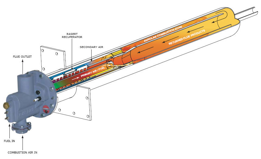
Principles of Operation
When the combustion air enters the 4748 RASERT™ burner, it is split into primary and secondary air streams. The primary air, which is approximately 25% of the total air, is combined with all of the fuel and is used to induce FGR (flue gas recirculation) from the flue. This air/fuel/FGR mix then travels down a tube in the center of the burner‘s integrated recuperator towards the flame stabilizer.
The secondary air stream also induces and mixes with FGR in the burner body. It travels down the outside of the recuperator towards the flame stabilizer. The integrated recuperator preheats the combustion air, fuel and FGR with heat recovered from the waste flue gas as it travels in the annular gap between the primary air tube and the outer wall of the recuperator casting. The actual secondary air preheat achieved is dependent on the application, but it is generally over 1100°F in furnaces running at 1600°F.
When the primary air (with added fuel & FGR) and secondary air (with added FGR) reach the stabilizer they are re-introduced and ignited in the annular space around the combustion tube and inside the stabilizer can. The stabilizer is designed to delay some of the combustion so the flame can be spread out along the length of the radiant tube, which helps provide uniform temperature distribution.
When the products of combustion reach the end of the radiant tube they enter the center combustion tube and travel back towards the recuperator and burner. When the flue gas reaches the burner body some of it is used as FGR and the rest exits through the flue outlet.
Preheated Air
The level of preheated combustion air is a major determining factor in the overall efficiency of a radiant tube combustion process. The higher the combustion air preheat the higher the efficiency and the greater the fuel savings. At the combustion air preheat levels of 1,050 – 1,300F, the combustion
efficiency ranges from 62-69% based on the higher heating value of the fuel. This increased efficiency results in fuel savings of up to 50% compared to conventionally fired ambient air burners.
The temperature of the preheated air generated by an internal recuperator is dependent on the flue gas temperature and flow, and the design of the heat exchanger element. The air in the 4748 RASERT™ burner is split into primary and secondary streams, that travel in separate paths through the heat exchanger elements. Approximately 75% of the air travels around the outside of the heat exchanger in the secondary air stream where the burner is operating at 16 osi air pressure with approximately 3% O2 in the flue gas exiting the burner.
Source: http://www.na-stordy.com/new-prods/4748_bul.pdf
More Information
NA-Stordy Combustion at www.na-stordy.com
Source: Text Bob Fegan 1/2009; Spinworks information from Spinworks presentation to the ESC Oct 2007; RASERT Burner information from North American Bulletin 4787 Oct 2006;
© 2008 Energy Solutions Center400 N. Capitol Street NWWashington, DC 20001 All rights reserved. Legal Contact our webmaster