
Steam Piping Best Practices
 Introduction
Just because it’s ‘been that way’ for a long time, don’t assume it’s right. In many cases steam systems were designed long before there was any concern about energy efficiency. Systems may have not been installed according to design because of some problem in the field – either something didn’t fit, got changed or an installer thought they had a better idea. Systems are often modified over the years; equipment, pipes and valves are moved so that they no longer perform in the way they were originally intended. All of these factors and more are reasons to expect that steam piping systems could be improved when the objective is better function and energy efficiency.
Problems with steam systems are not always obvious as equipment may continue to function, although impaired. Some problems lead to premature failure of equipment, but it may not be obvious what the cause of the failure was.
If a facility has not had a thorough review of its steam distribution system by a competent expert, then there are likely many things that an audit would reveal. The following examples are common problems discovered in the course of steam system audits by Duane Hagen of Merlo Steam (see links below). These are real facilities that in many cases were in improper operation for a number of years prior to the audit.
Problems and Fixes
 Steam Trap Installed Wrong
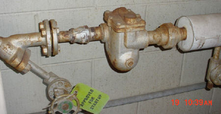
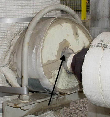
It is clear from the picture that this trap has been here a long time. What is not so obvious to the untrained eye, is that this trap is installed wrong.
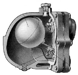
This trap is a ‘Float and Thermostatic type. It must be installed so that the bolted-on flat plate is in a vertical position. When it is horizontal as in this installation, the float is not a float but a pendulum (See the sectional illustration to the right).
When steam traps are improperly installed, they cannot function properly and therefore either do not remove the condensate, let steam blow through, or both.
 Other Components Installed Wrong
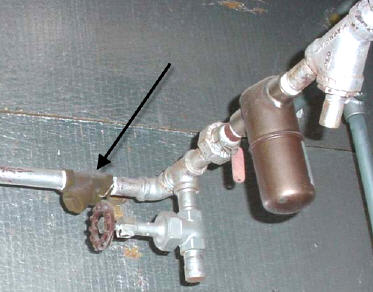
It is common to find many types of steam system components installed incorrectly. In this example, a mechanical check valve that requires gravity to operate properly is installed upside down. It is impossible for this check valve to function when installed this way.
However, it is probably a good thing that it is upside down, as it is also installed backwards. If it were installed upright, it would block flow in the wrong direction.
 Failed Valves
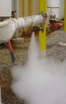
This valve is obviously stuck partly open. However, often valves are installed with pipe on the down-stream side. As in the picture, steam still blows past the valve, but since its inside of pipe, it’s not obvious.
Valves fail due to wear, corrosion and dirt/contaminates stuck in the valve seat.
 High and Low Pressure Systems Interconnected
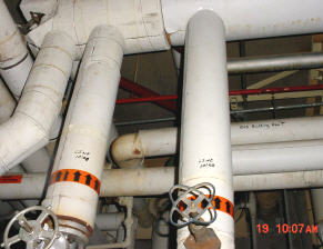
In facilities with high and low steam operating pressure systems, all steam and condensate lines should be properly identified and checked. Be sure that high and low pressure systems are not interconnected at any location, even on condensate systems.
High pressure condensate can flash to steam in low pressure condensate systems causing problems with their operation and wasting steam. Use a flash steam recovery system to flash high pressure condensate to steam and then inject the steam into the low pressure steam system.
 Supply Lines and Condensate
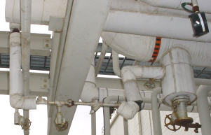
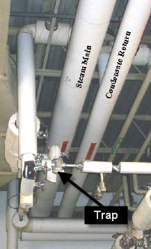
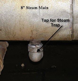
Long steam supply lines should be trapped to remove condensate and keep the steam dry. In the photo to the right, there is a steam trap off the steam main, and condensate is returned to the to the top of the condensate pipe. However, the steam trap is piped off the TOP of the Steam Main. Because condensate is on the bottom of the pipe, this trap is doing nothing to help keep the line dry.
Worse, not only is it not removing condensate, it is actually wasting energy. Steam comes off the top of the Steam Main, comes down to the trap along the vertical pipe in the left of the photo, as it is cooled by heat loss from the pipe. This steam trap is therefore acting mostly as a “steam cooler” wasting steam from the Steam Main.
Note the nice insulation job however; this is probably keeping the problem from being much worse.
Condensate should always be drained from the BOTTOM of the steam line in low sections of pipe and at changes in direction, such as a 90 Degree turn. Condensate from steam traps should always be returned to the TOP of condensate lines; the maximum height of rise above the steam trap to the condensate line is a function of steam pressure and the type of trap. A general rule of thumb is that 1 psi of steam will raise water about 2 feet. For example, a 5 psi system should not have condensate lines higher than 10 feet above the steam trap.
 Properly Size Steam Trap Drip Leg Lines
Not only must steam traps be piped off the bottom of the steam lines, the pipe must be properly sized. If the condensate drip legs are too small, the condensate will simply blow past the drain line.
Condensate drip legs should be sized according to the line they are draining. See the Chart for suggested sizes.
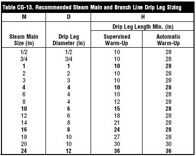
Source: Armstrong International
See also Condensate Return
 Control Systems
In order for steam system controls to function properly, they must be installed properly.
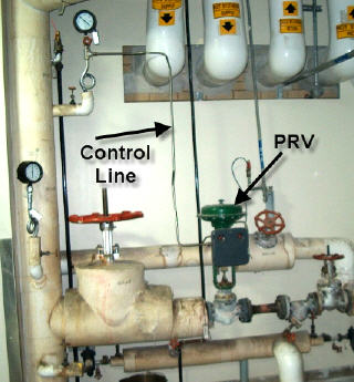
In the photo to the right, a green-headed PRV (Pressure Reducing Valve) has been installed to reduce the higher pressure steam from the main steam header, to a lower pressure for use in a low pressure application – such as space heating.
This type of PRV requires a down-stream sensor line to monitor the pressure and supply a check pressure back to the PRV.
The problem is that the control line is installed vertically higher than the PRV, resulting in the line going downhill back to the PRV. There is no place for the condensate to drain through the PRV, so it will fill/flood with condensate. When this happens, the PRV cannot accurately control the low pressure and premature failure of the PRV will likely result as it constantly chatters attempting to control the pressure.
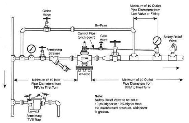
The correct way to install a PRV is shown in the above diagram. There must be a minimum distance between the PRV and sensing point, and the control line must slope down to the pipe – NOT the PRV, so that condensate will drain back to the steam line where it will be removed by a steam trap.
NOTE: There are also internally monitored PRV valves that do NOT require an external sensing / control line. Therefore, do not be alarmed if the PRV has no sensing line; but if it has a line, be sure that it is installed correctly.
 Water Hammer
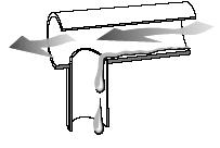
Water hammer is the result of condensate not being removed from long runs of steam lines. Steam moving through a line at high speeds picks up condensate in the bottom of the pipes, much like wind blowing across a lake forms waves. When the high speed steam and condensate come to a bend, such as a ‘Tee’ or 90 Degree turn, the steam makes the transition, but the water slams into the side wall of the pipe. A pulsing action results in a hammer-like action called ‘water hammer’. Water Hammer can destroy controls, insulation, pipe, break fittings, and cause a lot of undesirable noise.
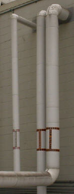
This photo shows evidence of water hammer at a ‘Tee’. Note that the insulation is gapping from the pipe – evidence that the pipe has been moving against the insulation, compressing it. The grey patches show an attempt to repair the insulation. There probably needs to be a steam trap installed on this line, or if there is a steam trap, it may not be working correctly.
 “Missing” Steam Traps
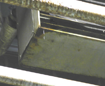
On the other side of this wall there is a long run of steam pipe; it then makes 2 sharp 90 Degree bends. The second bend, the lower one in the photo, would be a good spot for steam trap to drain condensate from the line.
 Leaking Equipment
Leaking steam coils, especially in equipment less than 30 years old, can be an indicator of improper seasonal shut-down, steam trap problems, or water hammer damage.
A closer inspection of this unit heater revealed that there was no way for the condensate to be drained out at the end of the heating season. Stagnate condensate can form a mild carbonic acid when CO2 comes in contact with water. This accelerates corrosion faster than water alone.
Steam systems should be piped to allow gravity drain-down when not in use, or should be blown out with compressed air at the end of each heating season.
Source: Thanks to Duane Hagen of Merlo Steam for providing these photos and an explanation of what the problem is and the best way to fix it. Duane and Merlo Steam conduct customized in-house training on steam system operation and perform steam distribution system audits. For information about an audit or training program, contact Duane at ![]() 269-833-7129, or see their web site at www.smithinstrument.com/Merlo/index.htm.
269-833-7129, or see their web site at www.smithinstrument.com/Merlo/index.htm.
Merlo Steam
35745 Beattie Drive
Sterling Heights, MI 48312
Telephone: ![]() 1-800-969-9779 FREE
1-800-969-9779 FREE