
Flue Gas Condensers
Introduction
Flue gases from large boilers are typically 450 – 650°F. Stack Economizers recover some of this heat for pre-heating water. The water is most often used for boiler make-up water or some other need that coincides with boiler operation. There is a class of economizers that are designed to condense the flue gases and/or have the water in direct contact with flue gases. I have called them ‘Flue Gas Condensers’. Stack economizers and Condensers should be considered as an efficiency measure when large amounts of make-up water are used (ie: not all condensate is returned to the boiler or large amounts of live steam is used in the process so there is no condensate to return) or there is a simultaneous need for large volumes of hot water.
The application difference between an economizer and condenser is that economizers are primarily used to heat a smaller volume of water to a high temperature for boiler feed water, and condenser units heat a larger volume of water to a lower temperature. Condensers can be more efficient because they can have a lower outlet exhaust temperature and take advantage of the energy in condensed flue gasses (the Latent Heat of Vaporization).
The savings potential is based on the existing stack temperature, the volume of make-up or hot water needed, and the hours of operation. Economizers are available in a wide range of sizes, from small coil-like units to very large waste heat recovery boilers. Condensers are available as small as 50 hp and a single condenser can be used on multiple boilers.
Some condensers have water in direct contact with the flue gases and others use heat exchangers. In some applications the water that has been in direct contact with the flue gases can be directly used; in other applications, the water must be passed through a heat exchanger before it can be used.
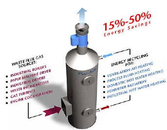
The key to the successful application of heat recovery is the ability to put the recovered heat to use. Uses include industrial process water heating, clean-up/wash-down water heating, laundry wash water, domestic water heating, space heating, snow melt and district heating systems. Potential Applications include: Greenhouses, Hospitals and Health Centers, Food processing, Schools and Universities, Laundries, Breweries, Hotels, Wineries, Government Buildings, and Swimming pools.
See also Economizers
Operation
In a direct contact unit, water is sprayed in contact with the flue gases, causing condensation and extracting most all of the heat. In units that have a heat exchanger, condensation is likely when there is enough water flow -or- at a cold enough inlet temperature to remove enough heat to cause condensation on the flue gas side of the heat exchanger. See the Manufacturer’s descriptions below for more details.

Economics
The savings potential is a function of how much heat can be recovered, which is a function of how much cold water needs to be heated. A generally accepted “rule of thumb” is that about 10% of boiler input capacity can be recovered with a properly sized condenser. This is a higher percentage than what can be recovered with an economizer because the water temperature is lower. However, there is also a lot more volume of water involved, assuming there is a need for enough cold water to condense all of the flue gas that is available. Therefore, for ‘ball parking’ purposes, start by comparing boiler input capacity with the need to heat water.
For example: consider a 500 hp boiler with a gas input of 20 million BTUs per Hour.
20,000,000 BTUs x 10% = 2,000,000 BTUs (100% Load Factor)
2,000,000 BTUs / (900 BTUs per Gallon of 160F water) = 2,200 Gallons per Hour
(2,000,000 BTUs / 80% efficiency) = ~2.4 MCF x $7.00 per MCF Natural Gas = $16.80 per Hour Value
Savings is reduced by 50% for a 50% Load Factor, etc.
If there is a need for that much hot water, the savings potential of $16.80 per hour would be multiplied by the number of boiler run hours, or the number of hours that the hot water can be used. In each application, be sure to consider the boiler Load Factor, the efficiency that the hot water is otherwise produced at, the cost of natural gas, and the installation cost of the equipment.
Condensers are generally NOT used to heat boiler make-up water. Use an Economizer for that application.
A condenser that recovers 10% of boiler input should easily have a 1 year payback in a year-round application.
More Information
DOE Tip Sheet – “Consider Installing a Condensing Economizer”PDF Format
DOE Tip Sheet – “Considerations When Selecting a Condensing Economizer” PDF Format
Manufacturers
 Kemco Systems
11500 47th Street, North
Clearwater, Florida 33762
Telephone: ![]() 800-633-7055 FREE
800-633-7055 FREE
Fax: 727-573-2323
Go to their web site atwww.kemcosystems.com
Typical gas fired heaters and boilers send up to 30% of the fuel they consume out the exhaust stack in the form of waste heat. This loss can mean that for every dollar spent on fuel the boiler system returns only 65 to 70 cents worth of useful heat.
Kemco’s revolutionary boiler Stack Economizer can easily recover over 80% of the waste heat found in the boiler’s exhaust. The dollars saved on the fuel bill in just one year can be enough to pay for the cost of the Economizer.
In some cases, the system reduced the flue gas temperature below the ambient combustion air, actually taking free heat from the air supply and, in effect, creating an apparent 100% efficient boiler system. Because the Economizer uses an external heat sink and can reduce the exhaust temperature of the stack to within 10° F of the inlet water temperature, the maximum amount of heat is extracted.
Traditional finned-tube and plain-tube units cannot reduce boiler or heater stack losses below 280° F without self-destructing from cold-end corrosion. But Kemco’s Stack Economizer safely reduces these stack gases as low as 40° F.
That’s because the gases from the boiler travel in a counter-flow pattern to the water, absorbing the heat and being pre-heated. There is a direct contact between the gases and the water, and because the final heat transfer mechanism is an “alternate surface” heat transfer, the stack gases can be cooled to within 5° F of the initial temperature of the inlet water.
This results in a double savings. First, the flue gas is cooled to a lower temperature with the Kemco system, so more sensible heat is taken from the dry flue gases, water and vapor. Second, heat energy is recovered from the heat of vaporization of the moisture formed during combustion by the fuel and the combustion air.
Sidel Systems USA
PO Box 1868
Atascadero, CA 93423
Telephone: ![]() 805-462-1250 or
805-462-1250 or
![]() 800-668-5003 FREE
800-668-5003 FREE
Go to their web site at www.sidelsystems.com
 Sidel Systems has been in operation in Canada since 1978, in the United States the company was incorporated in 1992. Sidel Systems specializes in the design and installation of hot water heating systems for commercial greenhouses.
The Sidel SRU series waste heat recovery units are built in North America in accordance with the ASME codes. An SRU flue gas waste heat recovery system can be installed with any natural gas or LPG fired power burner boiler or heating unit. When the heating unit is required to operate on oil the flue gases will have to be bypassed from the waste heat recovery unit. Flue gas recovery systems have been used around the world for over 20 years. In most applications savings of 12-15% are realized.
Standard sizes are for equipment with inputs from 2.1 to 42 million BTUper hour, 50 to 1,000 Boiler Horse Power.
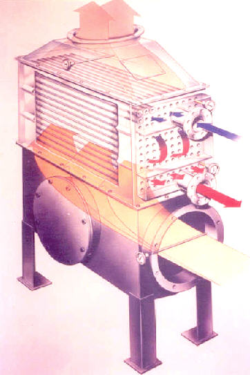 The waste heat recovery unit is designed to transfer the waste heat from the forced draft heating unit into usable heat. The waste flue gases from the heating unit are redirected to the recovery unit, which is placed beside the heating unit or alongside the unit’s chimney. The recovery unit cools the flue gases to the point where sensible as well as latent heat is recovered.
The waste heat recovery unit is a finned tube heat exchanger. The hot waste flue gas is diverted into the bottom receiver of this unit and then flows upwards across and through a series of specially designed finned tubes. The water that is being heated flows on the inside of these tubes. The SRU series is designed so that waste flue gas temperatures even below the water dewpoint (58C – 136) can be reached.
The SRU waste heat recovery unit has a large gas-side heat transfer surface of aluminum fin tubes, with the fins and the tubes formed as one piece. Pure aluminum is a very good heat conductor; is it also exceedingly resistant to the mildly acidic flue gas condensate. The aluminum fin tubes are fitted around a stainless steel tube. Stainless steel is used to prevent corrosion on the waterside surface. Compared to other materials, stainless steel will not allow the build-up of iron particles, which would act as an insulator on the tube surface.
Because of the high conducting properties of aluminum, the fins on the heating tubes are very thin. This allows more room for the flue gases to pass through. The result is an optimal ratio of the flue gas flow with respect to the fin surface area, which keeps the resistance of the flue gas heated side low. Because there is only a small increase in pressure, in most cases the heating unit is still capable of using its existing blower fan.
Thermal Energy International Inc.
36 Bentley Avenue
Ottawa, Ontario, K2E 6T8 Canada
Telephone: ![]() 613-723-6776 Fax: 613-723-7286
613-723-6776 Fax: 613-723-7286
Go to their web site atwww.thermalenergy.com
FLU-ACE® can be configured to handle any volume rate from boilers fueled by natural gas, oil, coal, or biomass. FLU-ACE® technology greatly improves the fuel efficiency of boiler operations, provides a significant return on investment, and reduces environmental emissions.
Up to 90% of the heat normally lost through boiler flue gas stack emissions is recycled by FLU-ACE® . This is possible because FLU-ACE®’s unique direct contact (gas/liquid) design enables optimal recovery of both sensible (dry) heat and latent (wet) heat, even in widely varying operating conditions.
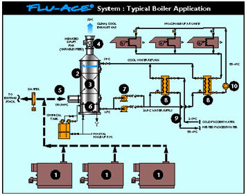
Conventional heat recovery technologies require a dedicated piece of equipment for each boiler exhaust. Now the varying flow of flue gases emitted from multiple boilers [1] can be efficiently processed by a single FLU-ACE® unit [2]. This means a lower initial investment, lower operating costs and a higher return on investment. FLU-ACE® will have an ongoing positive effect on your bottom line throughout its long operating life.
FLU-ACE’s unique internal structure [3] ensures maximum condensing heat and mass transfer. It also enables an unobstructed flow of liquids and gases through the tower, guaranteeing virtually continuous operation with limited downtime.
FLU-ACE® is equipped with a variable speed, induced draft fan [4] at the tower outlet to automatically maintain the optimum flue gas static pressure set point at the tower inlet [5].
Primary hot water is produced when boiler flue gas heat and pollutants are transferred and water vapor is condensed in the FLU-ACE®. The primary water (at up to 63°C/145°F) accumulates in the receiver [6] where it is chemically treated to neutralize acids.
FLU-ACE® uses variable speed pumps [7] to keep the temperature of the hot primary water leaving the receiver at the desired level. Control valves regulate distribution of the primary water to the heat exchangers [8] where the heat is transferred either to secondary water [9] (for direct process make-up or boiler make-up usage) or to secondary glycol fluid [10] (for direct plant make-up air heating or boiler combustion air preheating).